 |
|
|
|
|
|
|
|
|
|
|
|
|
|
|
|
|
|
|
|
|
|
|
|
|
|
|
|
BED AND PLATEN PRINTING MACHINES (continued)
|
|
|
|
|
|
|
|
|
|
|
A vertical windlass, under the rear of the press, moved the carriage via straps. The windlass was started, stopped and reversed by the alternate engagement of one or the other of two bevel wheels driven from the bevel wheel on the mainshaft. Shifting was effected by a long rocking lever, pivoted at its center, with a fork on its inner end to manipulate the gears and a roller at its other end which followed a meandering groove in the rim face of the carriage-motion control cam on the mainshaft.
|
|
|
|
|
|
|
To mitigate the shock-loading inherent in such an arrangement, the windlass drum was formed like the scroll-drum found in spinning mules or clockwork and provided an early start and stop at each stroke of the bed. The bed rested under the platen during the impression, then ran out under the inking rollers, reversed and ran in under the toward the platen for the next impression.
|
|
|
|
|
The frisket frame and the inner end of the tympan were attached to a rod at the inner end of the bed (opposite to handpress practice). The rod was not attached to the bed itself, but to the inner ends of two horizontal slides which were held loosely in guides upon the bed sides. Weighted cords were attached to the outer ends of the slides to keep them in their outermost position. The bed had to travel almost twice as far as the tympan/frisket assembly in order to pass fully beneath the inking rollers. As the bed came out from under the tympan, the slides following along until they struck fixed stops on the machine frame, which halted the tympan/frisket assembly in feeding position while the bed continued out to its point of reversal, when, on its inward travel, it took up the slack in the slides and pulled the tympan/frisket assembly with it under the platen.
|
|
|
|
|
The tympan was really just a 26" square of cotton fabric doubled over the inner rod, with the outer ends sewn together over another rod. This outer rod was held just outside the edge of the platen, when the bed was under the platen, by cords running up to the press head beam (or room ceiling) and thence over pulleys to two weights which served to keep the 'tympan' taut. Blankets and other packing were inserted into the cotton fold. When the bed was out, the tympan was held vertically out of the feeder's way.
|
|
|
|
|
As the bed came out, the tympan rose vertically and the frisket frame rode up inclined slides on the press frame so that the sheets could be exchanged. Beneath the slides were the ink fountain and ink rollers. A revolving disc affixed to the outer end of the bed acted as the distribution surface, just as in the familiar platen job press. The disc was turned by a ratchet wheel attached to its underside contacting a pawl fixed to the press frame. The fountain was operated from a pin on the vertical shaft. The quantity of ink supplied was regulated by raising or lowering the ductor roller in the fountain trough.
|
|
|
|
|
The Treadwells were built in Phineas Dow's Boston shop, under the eagle eye of Seth Adams. They evolved into a more compact single, a back-to-back double with impression made through motion of the platens, a later double with impression made through lifting the beds against stationary platens, and eventually a double-ender with a single reciprocating frisket carriage bearing two friskets taking impressions from a single forme. This last version was built by the Adams brothers after formation of their firm in 1830. (See 'Adams 1830' below)
|
|
|
|
|
|
|
XXXXXXXXXXXXXXXBooth, 1822, [U.S.A.]
Ralph Green's article describes Booth's first machine (1822) as a double ender, with two friskets and a single type-bed. In addition to the reciprocation of the friskets to present first one sheet and then the other to the action of the platen, the single type bed was reciprocated under the inkers. The wooden frame of this machine proved too weak for the constant starting and stopping of the heavy bed. Later machines were fitted with a stationary bed. Booth's business was confined to New York. He gained a U.S. patent in 1829, but did not continue in the press-building business.
|
|
|
|
|
|
|
XXXXXXXXXXXXXXIAdams, 1830, [U.S.A.]
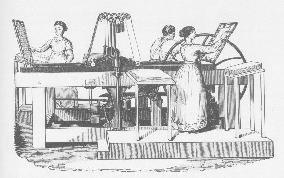
A wooden frame double-feeder printing from a single form, the press embodied three features integral to the later classic 1836 Adams: Toggle-driven bed rising against a fixed platen to take the impression, roll-away platen to expose the forme, and reciprocating carriage transporting friskets and forme rollers. Isaac Adams received a U.S. patent on 4th October 1830, comprising specification but no drawings. The specification describes an early version of the press, with some variation from the form depicted in our illustration of a late model. The press was made in platen size 20" x 26", and measured about nine feet long, three feet wide and four feet in height.
|
|
|
|
|
|
|
 |
|
|
|
The 1830 machine's carriage was a light wooden structure reciprocating upon slides in the upper frame rails. A frisket frame was placed on each end of the carriage; the two forme rollers were positioned in bearing boxes between the friskets, receiving ink from distributing drums and rollers on each side of the bed. The early presses were fitted with a fountain serving each distributing drum; later versions, as illustrated, made do with just the one.
|
|
|
|
|
|
|
|
|
A crank in the vertical drive shafting (at right, in the illustration) straightened the toggle via a connecting rod to raise the bed. A grooved cam on the shaft controlled the axial motion of the distributing drums through a long lever. Atop the drive shaft was an independent crank driving the carriage, arranged to allow the carriage to pause at each end of its travel so that the impression could be taken on the sheet on one frisket while the sheets where changed on the other.
|
|
|
|
|
|
|
The hinged, frisket-like frames seen at the ends of the press, called by Adams "fly-frames", were fitted with points upon which the fresh sheets were placed. As her frisket came out, the feeder removed the printed sheet. When her frisket came to rest, the fly-frame at her end was mechanically turned down upon the frisket, impaling the fresh sheet upon the frisket points, and was then mechanically returned to its upright position as her frisket began to move towards the platen. The wages of a taker-off were saved. The fly-frame developed into the sheet-delivery fly of the 1836 Adams.
|
|
|
|
|
|
|
Brothers Seth and Isaac Adams formed a Boston company in 1830 to manufacture the press; both were veterans of Phineas Dow's workshop and familiar with Treadwell's presses. They promised 1000 impressions per hour from their Treadwell-inspired machine, which appeared in suppliers' catalogues as late as 1850.
|
|
|
|
|
|
|
XXXXXXXXXXXxXXXTufts, 1834, [U.S.A.]
Phineas Dow's colleague Otis Tufts received a US patent 22 August 1834, specifications and drawings, for a bed and platen machine. The NMAH Smithsonian has a patent model, a photo of which can be seen on their website. A description appears in Elizabeth Harris's Patent Models in the Graphic Arts Collection. See also letters held by the National Archives, Washington, D.C., supporting Adams' request for extension of the 1836 Adams patent. From Tufts and other leading printers and printers' engineers, the letters contain much information about the manufacture, distribution and use of early machines in the U.S.A.
|
|
|
|
|
|
|
The Tufts press's platen was drawn down upon the stationary bed by toggles beneath the bed acting upon a stout crossbar below. Impression rods linked crossbar and platen. The platen rolled back to expose the forme. A reciprocating carriage bore two forme rollers and the frisket. The tympan was affixed to the platen. Although a single-ender, the press used two friskets, one remaining in the feeding position while the other was under the platen. On its return, the carriage released the frisket with its just-printed sheet and engaged the other frisket, upon which a fresh sheet had just been pointed, taking it under the platen while the attendants switched sheets on the exposed frisket.
|
|
|
|
|
|
|
Ink distributing drums and fountain were situated at the front of the press. Impression, carriage motion and the "elevators" for positioning the "out" frisket were driven from several rotating cams on the camshaft. Despite their complexity, these presses were much admired at the time of their introduction and a number were put to work, but the appearance in 1836 of the improved Adams brought sales to a halt.
|
|
|
|
|
|
|
|
|
|
|
|
|
|
|
|
|
|